Goal:
To create a robot arm that is able to move to specific angles or positions using two servos and an Arduino.
Planning/Design Proposal:
Overall Objective
I will create a program in the Arduino ide program that moves a robot with two joints to a desired position when coordinates are input into the program. This robot will be designed using 3d printed parts.
Who is involved?
Alex Racel
What resources will your team need?
I will just need a few screws and 2 servos.
Include the following:
X and y are the coordinates for the end effector position
Joint 2 = arccos((x^2+y^2-5^2-5^2)/(2*5*5))
Joint 1 = arctan(y/x)-arctan((5*sin(joint 2))/(5+5*cos(joint 2)))
Fk
Q1 and Q2 represent the given joint angles
Link 1 endpoint = (5cos(Q1), 5sin(Q1))
Link 2 endpoint = (5cos(Q1)+5cos(Q1+Q2), 5sin(Q1)+5sin(Q1+Q2))
I will create a program in the Arduino ide program that moves a robot with two joints to a desired position when coordinates are input into the program. This robot will be designed using 3d printed parts.
Who is involved?
Alex Racel
What resources will your team need?
I will just need a few screws and 2 servos.
Include the following:
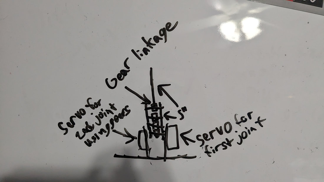
- An accompanying sketch or model of your robot. On this include specific measurements for leg lengths as well as the:
- Forward kinematic equations
- What the end effector position will be for given joint angles
- What the end effector position will be for given joint angles
- Inverse kinematic equations
- If analytical: What joint angles will need to be set to reach a given end-effector position
- If numerical: nothing needed. Just say you are using a numerical approach
- If analytical: What joint angles will need to be set to reach a given end-effector position
- Forward kinematic equations
X and y are the coordinates for the end effector position
Joint 2 = arccos((x^2+y^2-5^2-5^2)/(2*5*5))
Joint 1 = arctan(y/x)-arctan((5*sin(joint 2))/(5+5*cos(joint 2)))
Fk
Q1 and Q2 represent the given joint angles
Link 1 endpoint = (5cos(Q1), 5sin(Q1))
Link 2 endpoint = (5cos(Q1)+5cos(Q1+Q2), 5sin(Q1)+5sin(Q1+Q2))
Create:
For the arm I designed it to be 3d printed within fusion 360. I then printed all of the parts and assembled the arm using screws and hot glue.


Test:
While the original design had both servos mounted on the base with gears going out to the second joint, I decided against this to simplify the design and make it easier to program. After building the final design I programmed the arm with the Arduino IDE app and was able to get the arm to move to either the desired position relative to the base or to specific angles. Overall I would say that this project was a success and that I was able to accomplish everything that I aimed to do.


